
Day 1: Network Architecture & Fundamentals
Introduction: Building the Modern Enterprise Network
At its core, a computer network is a connected collection of autonomous computing devices capable of exchanging data and sharing resources. Whether you are loading a web page, streaming a video, or sending a command to a cloud server, data moves across a series of structured hardware devices and physical mediums. For the CCNA 200-301 exam, mastering how these core components interact within standardized network topology architectures is your essential starting point.
In this deep dive, we break down the primary hardware components that power enterprise networks, explore modern two-tier and three-tier hierarchy models, and contrast traditional on-premise infrastructure with modern cloud deployment models.
Key Infrastructure Components Explained
1. Routers
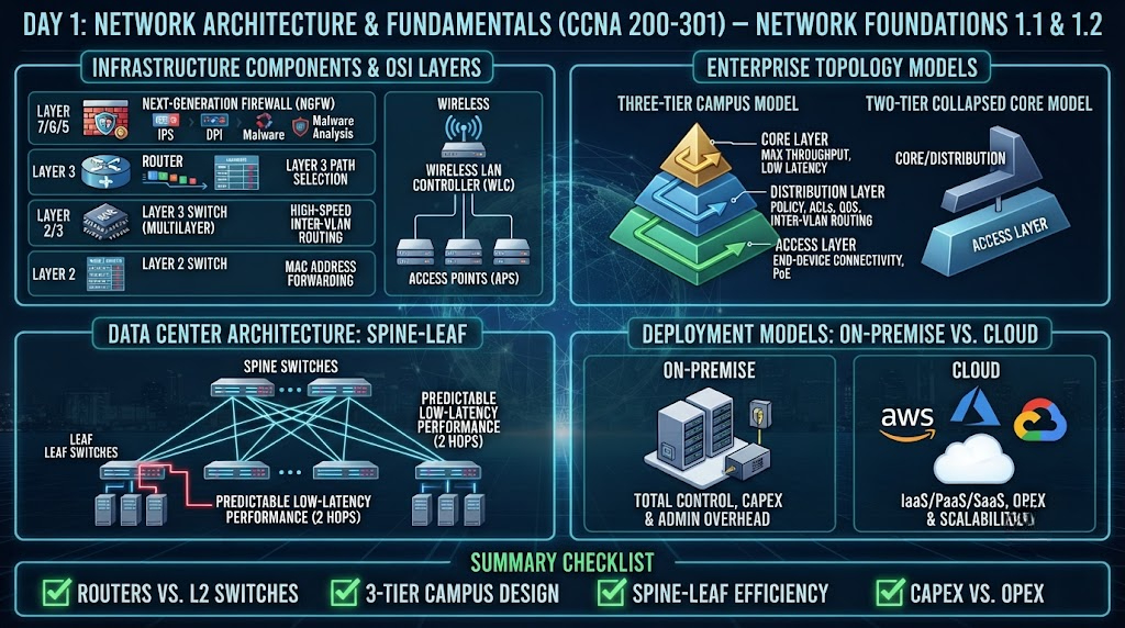
A router operates primarily at Layer 3 (Network Layer) of the OSI model. Its primary responsibility is to forward IP packets between different logical networks. Routers analyze the destination IP address inside an incoming packet, query their routing table, and determine the optimal next hop path. Beyond path selection, routers establish broadcast boundaries; unlike switches, routers do not forward Layer 2 broadcast frames by default.
2. Layer 2 and Layer 3 Switches
- Layer 2 Switches: Work at the Data Link Layer. They use Media Access Control (MAC) address tables to forward frames within a single Local Area Network (LAN) or Virtual LAN (VLAN). When a Layer 2 switch receives a frame, it reads the destination MAC address and forwards it out the specific port associated with that MAC.
- Layer 3 Switches (Multilayer Switches): Combine high-speed Layer 2 hardware switching with Layer 3 routing functionality. They perform Inter-VLAN routing at wire speed using specialized hardware known as Application-Specific Integrated Circuits (ASICs).
3. Next-Generation Firewalls (NGFW) & IPS
Traditional firewalls examine traffic based on basic parameters like source/destination IP addresses and TCP/UDP ports (Layers 3 and 4). A Next-Generation Firewall (NGFW) adds deep packet inspection (DPI) up to Layer 7 (Application Layer). NGFWs integrate Intrusion Prevention Systems (IPS), malware analysis, encrypted traffic inspection, and user-identity tracking to block modern cyber threats in real time.
4. Wireless Access Points (APs) & Controllers (WLC)
- Access Points (APs): Transmit and receive radio frequency (RF) signals to connect wireless client devices to the wired network.
- Wireless LAN Controllers (WLC): centralize the management, security, and configuration of multiple lightweight access points across an enterprise environment.
Enterprise Topology Architectures
Designing a reliable network requires structural hierarchy. Cisco recommends standardized architectural frameworks to ensure scalability, fault tolerance, and manageable traffic flows.
The Three-Tier Campus Model
The traditional enterprise design divides the network into three distinct layers:
- Core Layer: The high-speed backbone of the network. Designed for maximum throughput and low latency, the core layer quickly moves large volumes of traffic between distribution blocks. Complex packet filtering and routing policies are generally avoided here to preserve speed.
- Distribution Layer: Acts as the boundary between the access layer and the core. It implements network policy, routing between VLANs, Access Control Lists (ACLs), security rules, and Quality of Service (QoS).
- Access Layer: The edge of the network where end-user devices (PCs, IP phones, wireless access points) connect. The access layer enforces port security, VLAN assignment, and Power over Ethernet (PoE).
The Two-Tier Collapsed Core Model
In small to medium-sized enterprise networks, the costs and complexity of a three-tier model may not be justified. In a Collapsed Core architecture, the functional roles of the core layer and distribution layer are merged into a single layer of powerful multilayer switches. The access layer switches connect directly to this combined Core/Distribution block.
Data Center Architecture: Spine-Leaf
In modern data centers, traffic patterns have shifted from vertical (north-south, between client and server) to horizontal (east-west, between server and server). The Spine-Leaf topology solves performance bottlenecks:
- Leaf Switches: Connect directly to servers and storage units. Every leaf switch connects to every spine switch.
- Spine Switches: Form the high-speed core. Spine switches only connect to leaf switches—never to each other or directly to endpoints.
This setup ensures that any server in the data center is always exactly two hops away from any other server, guaranteeing predictable, low-latency performance.
Deployment Models: On-Premise vs. Cloud
- On-Premise Infrastructure: The organization owns, houses, and maintains physical servers, switches, routers, and power systems inside its own building or private data center. This offers total administrative control but requires substantial Capital Expenditure (CapEx) and operational overhead.
- Cloud Infrastructure (IaaS/PaaS/SaaS): Computer resources, network appliances, and storage are provided off-site by third-party vendors (such as AWS, Azure, or GCP) over the Internet. It shifts financial models toward Operational Expenditure (OpEx), allowing organizations to scale bandwidth and compute dynamically.
Summary Checklist for CCNA Day 1
- [x] Understand the functional role of Layer 2 switches vs. Layer 3 routers.
- [x] Memorize the roles of Core, Distribution, and Access layers in campus design.
- [x] Identify why Spine-Leaf topology is preferred for East-West data center traffic.
- [x] Distinguish between On-Premise CapEx and Cloud OpEx models.