
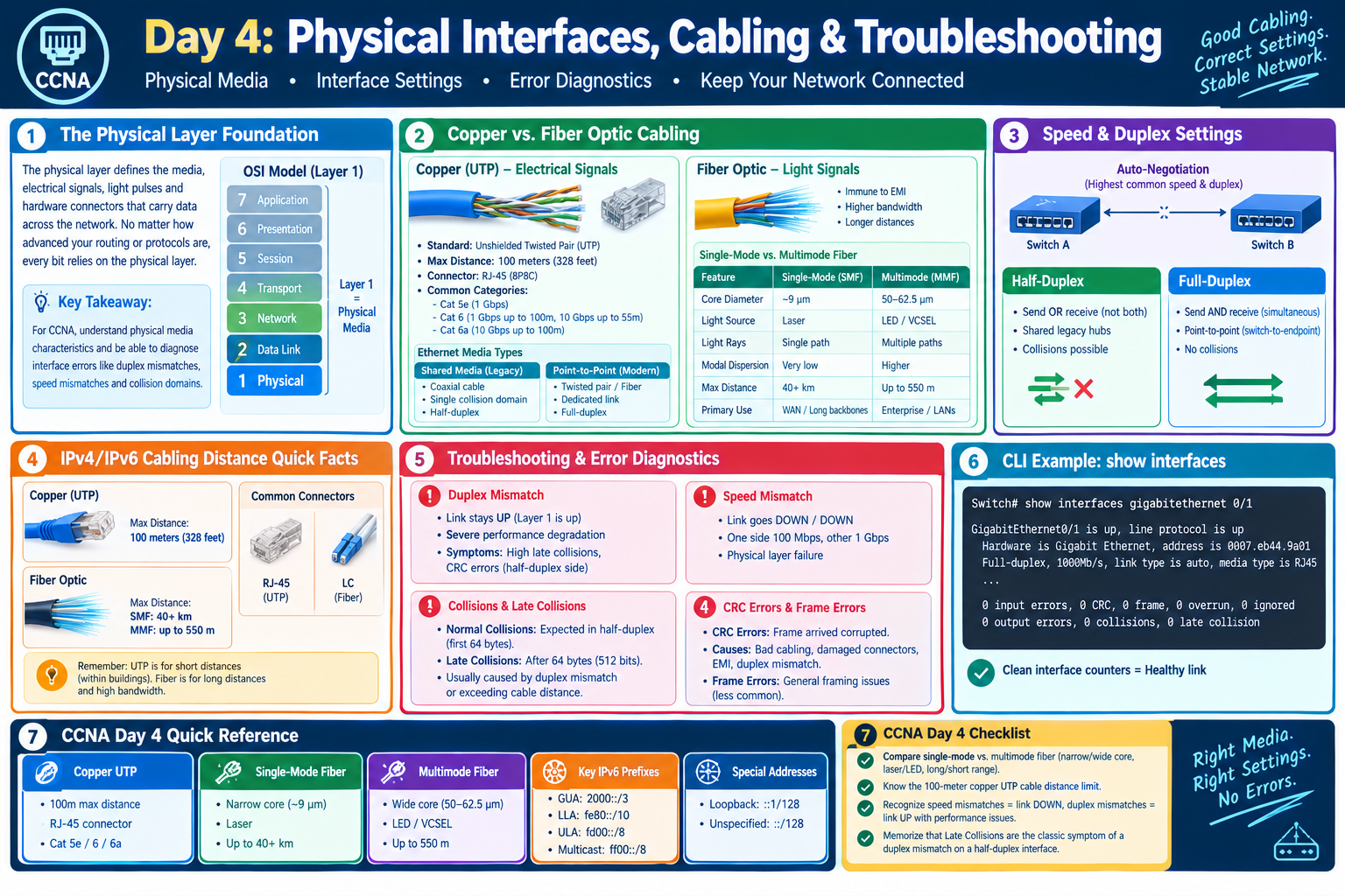
Day 4: Physical Interfaces, Cabling & Troubleshooting
Introduction: The Physical Layer Foundation
No matter how sophisticated your network protocols, routing tables, or software definitions are, every bit of network data ultimately relies on physical transmission. Layer 1 of the OSI model defines the physical media, electrical signals, light pulses, and hardware connectors that form the foundation of corporate communications.
For network engineers preparing for the CCNA exam, understanding physical media characteristics—such as copper Ethernet cabling versus single-mode and multimode fiber—is essential. Equally critical is the ability to diagnose physical layer interface errors like duplex mismatches, speed mismatches, and collision domains.
Copper vs. Fiber Optic Cabling
Network media falls into two primary physical categories: Copper cabling, which transmits electrical pulses, and Fiber-Optic cabling, which transmits light pulses generated by lasers or LEDs.
1. Copper Cabling: Unshielded Twisted Pair (UTP)
UTP cable is the standard choice for horizontal cabling within office spaces, connecting end-user endpoints (PCs, IP phones, printers) to access layer switches.
- Standard Distance Limit: 100 meters (328 feet) max total distance before signal attenuation degrades performance.
- Connector Type: RJ-45 (8P8C connector).
- Common Categories: Category 5e (1 Gbps), Category 6 (1 Gbps up to 100m, 10 Gbps up to 55m), and Category 6a (10 Gbps up to 100m).
- Ethernet Shared Media vs. Point-to-Point: Early Ethernet networks used coaxial shared media where all devices shared a single collision domain. Modern Ethernet uses full-duplex point-to-point connections directly between dedicated switch ports and endpoints.
2. Fiber-Optic Cabling
Fiber-optic cables use a glass or plastic core to transmit light signals, providing immune resistance to Electromagnetic Interference (EMI) and supporting significantly higher bandwidth over long distances.
| Characteristic | Single-Mode Fiber (SMF) | Multimode Fiber (MMF) |
| Core Diameter | Very narrow (~9 microns) | Wider (~50 to 62.5 microns) |
| Light Source | Laser | LED or VCSEL |
| Light Rays (Modes) | Single straight light path | Multiple dispersed light paths |
| Modal Dispersion | Extremely low | Higher (limits maximum distance) |
| Max Distance Range | Up to 40+ kilometers | Up to 550 meters (typically) |
| Primary Deployment | WAN links, long campus backbones | Enterprise building backbones, LANs |
Common Interface Settings: Speed & Duplex
Modern Ethernet switch ports support Auto-Negotiation, allowing two connected devices to automatically select the highest mutually supported speed (e.g., 100 Mbps vs. 1000 Mbps) and duplex mode (Half-Duplex vs. Full-Duplex).
- Half-Duplex: Devices can send OR receive data, but not simultaneously. Shared legacy hub environments operate in half-duplex, making collisions possible.
- Full-Duplex: Devices can send AND receive data simultaneously. Point-to-point connections to switch ports operate in full-duplex, completely eliminating collisions.
Physical Layer Troubleshooting & Error Diagnostics
When physical interface settings fail or cables degrade, network performance plummets. Below are the core physical error counters monitored via the Cisco IOS CLI command show interfaces:
1. Duplex Mismatch
A Duplex Mismatch occurs when one side of an Ethernet link is manually hardcoded to Full-Duplex while the opposite side is set to Auto-Negotiation (or Half-Duplex).
- Behavior: The link remains physically UP (Layer 1 is up), but network throughput becomes severely degraded with extreme packet loss during heavy traffic.
- Symptoms in CLI: The half-duplex side reports high numbers of Late Collisions and CRC Errors, while the full-duplex side reports FCS Errors or generic framing errors.
2. Speed Mismatch
Occurs when one side of a cable operates at 100 Mbps and the other operates at 1000 Mbps (1 Gbps). Unlike a duplex mismatch, a speed mismatch causes the physical link to go DOWN / DOWN (Layer 1 failure).
3. Collisions & Late Collisions
- Normal Collisions: Expected behavior in legacy half-duplex environments when two devices transmit simultaneously within the first 64 bytes of a frame transmission.
- Late Collisions: Occur when a collision happens after the first 64 bytes (512 bits) of a frame have been transmitted. Late collisions are almost always caused by a duplex mismatch or exceeding maximum cable distance limits.
4. CRC Errors & Frame Errors
- Cyclic Redundancy Check (CRC) Errors: Indicate that a frame arrived corrupted. This is typically caused by bad physical cabling, damaged RJ-45 connectors, severe electromagnetic interference (EMI), or a duplex mismatch.
Physical Interface Diagnostics CLI Summary
Plaintext
Switch# show interfaces gigabitethernet 0/1GigabitEthernet0/1 is up, line protocol is up Hardware is Gigabit Ethernet, address is 0007.eb44.9a01 Full-duplex, 1000Mb/s, link type is auto, media type is RJ45 ... 0 input errors, 0 CRC, 0 frame, 0 overrun, 0 ignored 0 output errors, 0 collisions, 0 late collision
Summary Checklist for CCNA Day 4
- [x] Compare Single-Mode Fiber (narrow core, laser, long range) vs. Multimode Fiber (wide core, LED, short range).
- [x] Know the 100-meter copper UTP cable distance limit.
- [x] Recognize that speed mismatches bring the link DOWN, while duplex mismatches keep the link UP with performance degradation.
- [x] Memorize that Late Collisions are the classic symptom of a duplex mismatch on a half-duplex configured interface.
Stay Connected With CareerValore
Blogs WhatsApp Channel – Daily Quizzes & Blog Updates
Join the CareerValore Blogs WhatsApp Channel
Telegram – Job Updates & Career Alerts
Join CareerValore on Telegram
WhatsApp – Daily Job Updates
Join the CareerValore Daily Job Updates Channel